|

|

|

|

|

|

|

|


Virtual Analog Synthesizer - Detailed Description
Contents:
Modes
My virtual analog synthesizer can work in three basic modes:
- Classical synthesis (waveform generator) with subtractive filtering -

- Additive synthesis with subtractive filtering -

- Additive synthesis with additive filtering -

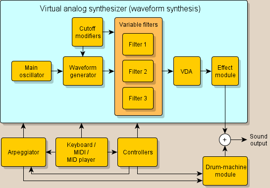
Classical synthesis (waveform generator) with subtractive filtering - the base signal is generated by a shape waveform generator (e.g., sine, rectangular, saw, ...).
Filtration is performed by digital filters that modify the signal and change its frequency composition (color).
Such a method of sound generation is implemented on most analog synthesizers.
Additive synthesis with subtractive filtering - the base signal is generated by summing up harmonic components - sines.
Properly adjusting the volume of the harmonic components makes it possible to generate an almost identical signal as the signal from the shape waveform generator.
This mode is computationally difficult and therefore it is possible to determine how many harmonic components to count (parameter "Harmonic count").
With fewer harmonic components, there is a lack of sound at high frequency.
Unlike the previous mode, however, it has one advantage - it is possible to vary the frequencies of the individual harmonic components (use e.g. when creating "ringing" or "metallic" sound).
Higher harmonic components are formed either as normal multiples of the first harmonic or one of three methods for their shift (linear shift, exponential shift, or manual setting of each frequency).
Filtering is performed as in the previous mode - it filters up the signal generated by summing up all harmonic components.
Additive synthesis with additive filtering - signal generation works similarly to the previous mode - the signal is generated by summing up harmonic components - sines.
However, filtering works differently - it does not process any resulting signal but instead determines the volume (i.e. amplitude) of the individual harmonic components.
The amplitude of the particular harmonic component therefore depends on the selected spectrum (e.g. the saw waveform) and the value given by the filter for this harmonic component.
The resulting signal is not filtered anymore.
It is possible to create filters that could not be created as classic filters (e.g. very high filter order).
However, this mode also has its disadvantages (more in the Filters section).
In the following description, it will be mentioned in which of these modes the description is concerned. However, some parts of the description are common to all three modes.
Modules
The following block diagrams illustrate the connection of synthesizer modules and other modules.
Block diagram of the synthesizer in classical synthesis with subtractive filtering (mode ):
Block diagram of the synthesizer in additive synthesis mode and subtractive or additive filtering (modes ):
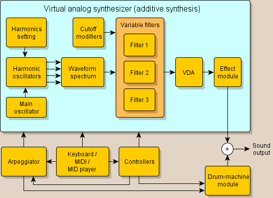
The frequency of the tone is created by a main oscillator, whose task is to determine the frequency based on the played tone, portamento, vibrato, oscillator envelope and so on.
Parts such as Arpeggiator, Controllers, and Drum-machine are additional program features.
Controllers
Controllers serve to control parameters of the synthesizer, the arpegger and the drum-machine either by special rotary knobs on the screen or by controlers via MIDI. To each controller can be assigned one of the control component (for example, the volume pedal, the joystick on the keyboard, etc.) and parameter of the synthesizer, the arpeggiator or the drum machine, which should be controlled. You can also set the range of the controlled parameter and slow the change.
Layers
My virtual analog synthesizer can work either in 1-layer mode or in 2-layer mode.
A layer is a block that produces the sound given by its complete set-up
In 2-layer mode, such blocks are two, and therefore when the tone is played, sound is produced that is the sum of two independent layers.
So the sound of each layer can be completely different.
The layers are independent of each other (except for the ability to synchronize layer 1 oscillator according to layer 2 oscillator).
Only the input is common (i.e. commands from keyboard, MIDI, NetSound, arpeggiator or controller) and the output is summed up and brought to the effect module.
The meaning of the layers is shown in the following figure:
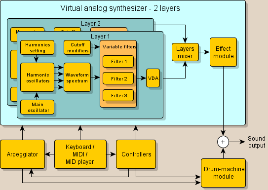
It should be mentioned that the number of layers is different from the number of sounds at once - polyphony. If polyphony is 4, at least 4 voices can be heard (but the setting is the same). However, each voice may contain one or two layers.
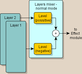
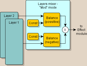
If the synthesizer is in 2-layer mode, the resulting signal can be obtained in two ways from single layer signals:
-
by adding - option "Normal (add)":
where the layer level is controlled by one "Layers 1/2 balance" knob - this determines their ratio.
-
by myltiplying - option "Mod (multiple)":
Here is the calculation a bit more complicated, but the "Layers 1/2 balance" knob again determines the ratio of the layer signals, but with the difference that the signals multiply. If the knob is turned to the left, only layer 1 is heard, when it is turned right, only layer 2 is heard, and if it is in the center, the sound is produced by multiplying the signals of both layers.
Oscillators
The oscillator module consists of one (classical synthesis with subtractive filtering ) or of two parts (modes of additive synthesis ):
- generator of the pitch of the basic harmonic component,
-
generator of the pitch of other harmonic components (only for additive synthesis modes ).
This means that the higher harmonic components do not have to be firmly bound to the basic harmonic component and their behavior can be set.
Generator of the pitch of the basic harmonic component is illustrated in the following figure:
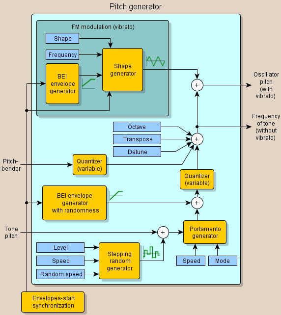
The main output of this module is in the picture called "Oscillator pitch" and it also includes vibrato. On the other hand, the output called "Frequency of tone" does not include vibrato and serves to control some other modules (e.g. filters or VDA modulation), where a parameter depends on the pitch of the played tone.
In this module there is a "BEI" evelope generator (BEI = Begin-End-Interval) having the following structure:
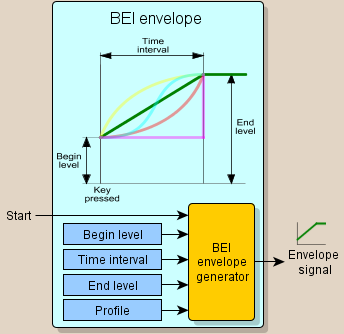
In the figure, various transition profiles between the start and end values are color-coded.
His similar module was in the picture called "BEI envelope with randomness" - the initial and final values may also be negative and, moreover, it is possible to set the randomness of the start and end values.
Generator of the pitch of other harmonic components and module of the harmonic oscillators illustrate following two figures (only in modes ):
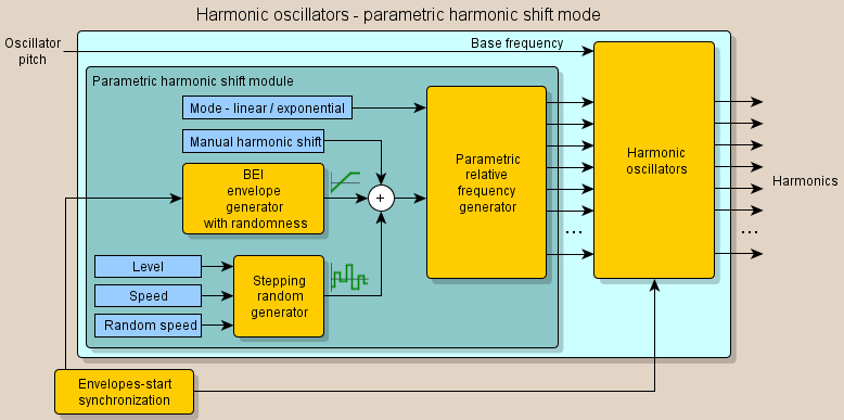
This figure shows a mode of parametric shift of higher harmonics - the pitch of other harmonics is determined by a certain mathematical calculation.
The next figure shows the mode of user-adjustable pitch of other harmonic components:
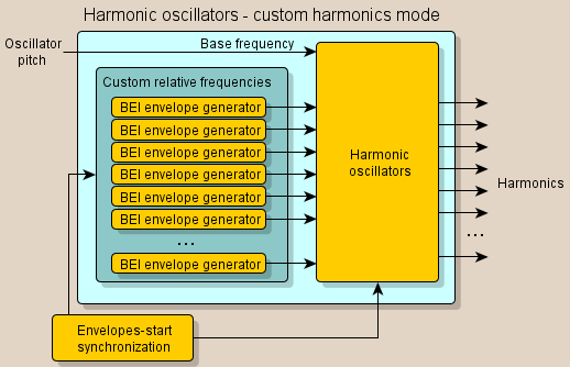
It should be noted that all "BEI" envelope generators have a common time interval parameter.
In this mode, the pitch of each harmonic component can be set separately.
The module of harmonic oscillators was the same in both modes and its role is to generate harmonic (sine) components whose frequency is determined by the frequency of the first harmonic component "Tone Pitch" and the relative frequency of each other harmonic component.
The oscillators can be synchronized with the start of envelopes - in this case when starting a tone all the oscillators begin to generate a sine waveform from zero.
This prevents the occurrence of a burst at the beginning of the tone (provided that the voice was in silence before it).
Spectrum generator ()
The task of this module is to produce the resulting signal from the harmonic oscillator signals. The amplitude of all harmonic components from the harmonic oscillators is the same, and a simple addition of these signals would not produce a reasonable result signal. Therefore, the amplitude of the individual harmonic components needs to be suitably adjusted, and it is possible to simulate the spectrum of known shape signals (saw, triangle, rectangle, etc.) This makes the spectrum generator module:
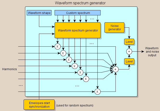
In addition to the spectrum of basic known signal shapes, it is also possible to select a user spectrum in which it is possible to set the amplitude of each individual harmonic component. There is also a random spectrum - this is always generated when the envelope is started.
Filters
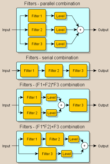
One of the most important parts of an analog synthesizer are filters. The synthesizer works with up to three independent filters that can be combined either in parallel, serial or one of two serial-parallel combination (see figure):
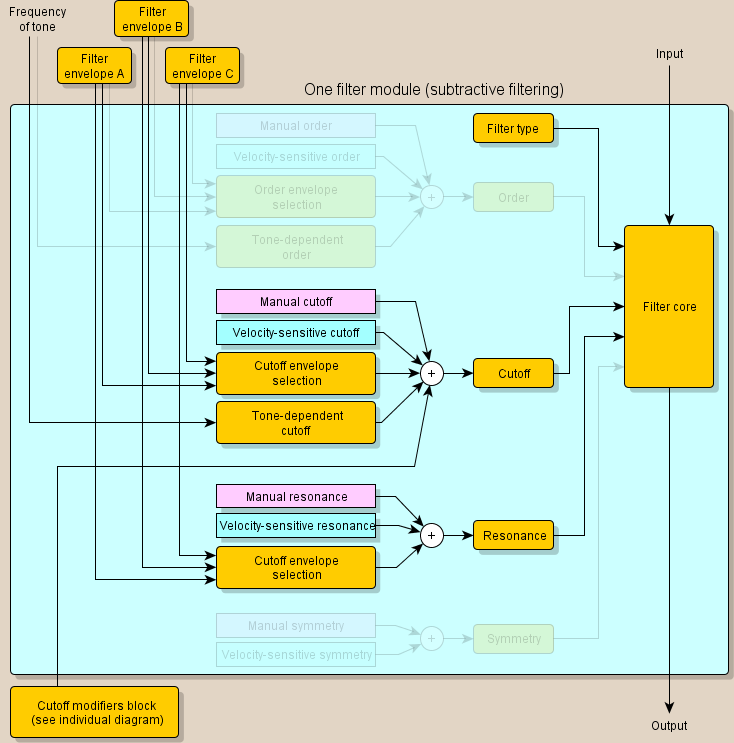
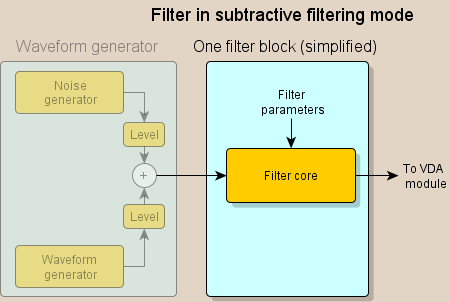
Block diagram of one filter in modes :
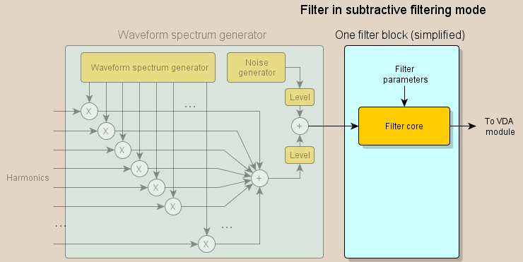
Block diagram of one filter in mode :
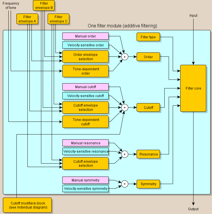
The filter works with basic parameters:
- Type - Low-pass filter with resonance,
High-pass filter with resonance,
Band-pass filter,
Pulse emulator (rectangular signal emulator with variable pulse width) - only in mode .
In addition, the options Off and All-pass are available.
- Order - filter order (i.e. its slope) - only in mode .
- Cutoff - cutoff (center) frequency. For Pulse emulator type, this parameter is changing the width of the emulated rectangular signal.
-
Resonance (only in the case of High-pass and Low-pass filter).
In modes it is also the quality of the Band-pass filter.
- Symmetry (only in the case of Band-pass filter) - only in mode .
Filter envelope modules (envelope A, B, and C) are common to all 3 filters, but each filter has one of the envelopes to choose from and also the intensity and polarity of the selected envelope.
Filter envelope (A, B or C) has the following structure:
It is also possible to choose the shape of the rising and falling edge - it can be either linear or exponential. It is possible to set the dependence of some envelope parameters on the key velocity value.
In the case of modes and it is possible to switch each filter to a "double" mode - in which case the filter core will be as two identical filter cores connected in serial:
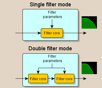
Simple filter has a 12dB/octave slope, double filter has a 24dB/octave slope.
Parameter "Cutoff" (center frequency) can change even so-called. modifiers:
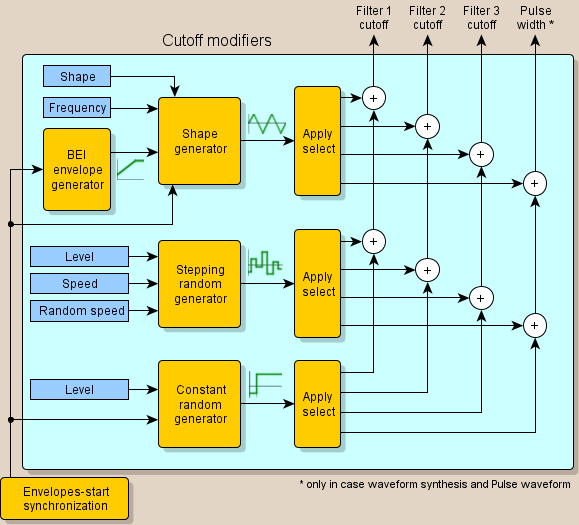
This module is common to all 3 filters.
The "Apply select" block allows you to link the specified modifier to filters or the pulse width parameter (only in mode and when Pulse shape is selected).
Three modifiers are available:
- Shape signal generator (optional shape, frequency and envelope). The envelope of this generator is always synchronized with the start of other envelopes (normally when starting a tone). The shape signal can also be synchronized with the start of the envelopes.
- Random signal generator at certain time steps. You can choose the speed of the steps and also the randomness of the speed of the steps.
- Constant random generator - the value is constant for the duration of the tone. When a new tone is triggered (at the start of all envelopes), a new random value is generated.
Note: starting envelopes may not be the same as the starting of a tone - in the case of a legato when a new tone starts but the envelopes do not restart.
Modes of filtering
Filtering in this virtual analog synthesizer can work in two completely different modes:
These two modes need to be more explained.
Mode of subtractive filtering - filters are actually blocks into which the signal enters and the filtered signal outputs.
Filtering in this mode means that something is being removed from the signal - of which the name "subtractive" filtering.
Filter principle in subtraction filtering in mode :
Filter principle in subtraction filtering in mode :
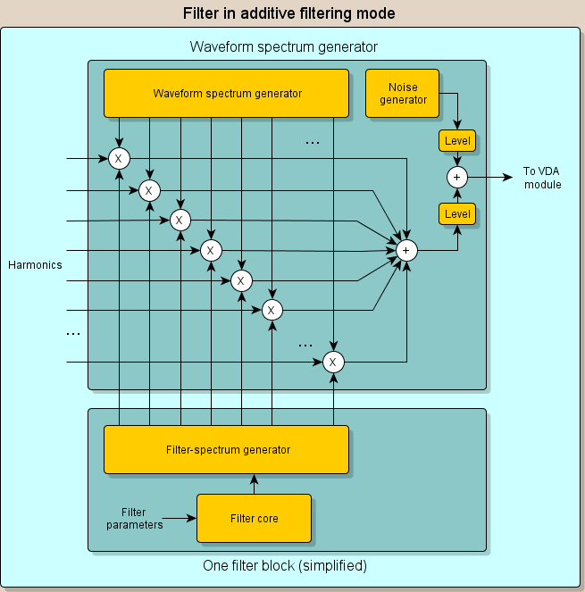
Mode of additive filtering works by computing the frequency spectrum of the filter combination as a set of values (one value for one harmonic component).
These values are multiplied by the amplitudes of harmonic oscillators (similar to what the spectrum generator does).
The following figure shows the filter principle in mode :
Apart from the difference in the principle of the filters in these two modes, the difference is also in the options. Each has its advantages and disadvantages:
| Advantages | Disadvantages | |
| Modes |
It is possible to filter the noise.
Better resonance performance. |
Smaller filter options (especially filter order).
Filters are affected in parallel combination (product of phase change). |
|---|---|---|
| Režim |
Better filter options.
Filters are not affected in parallel combination. |
No noise can be filtered.
Less realistic resonance. |
VDA
VDA (Variable-Digital-Amplifier) is the signal amplitude processing module. Immediate amplitude is determined as follows:
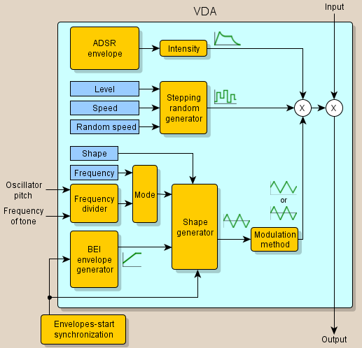
The modules of "BEI" envelopes, the stepping random generator, and the shape signal generator are the same as for filter modifiers.
In the case of the shape signal generator, it is possible to set the modulation method:
- Standard - classical amplitude modulation,
- Myltiplying - the modulated signal is directly multiplied by the shape signal. Since the shape signal is both positive and negative, the modulated signal is multiplied by a positive one, one negative value, resulting in signal inversion.
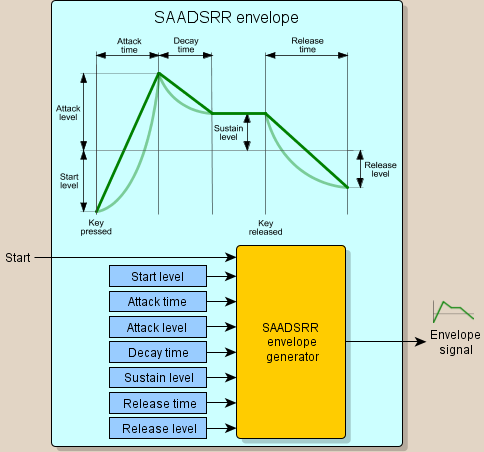
"ADSR" envelope module (Attack-Decay-Sustain-Release) is illustrated in the following figure:
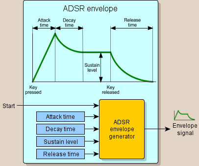
The rising edge is always linear and the declining edge is always exponential. Additionally, it is possible to set the envelope intensity as well as the dependence of this intensity on the key velocity. It is also possible to adjust the dependence of some other "ADSR" envelope parameters on the key velocity.
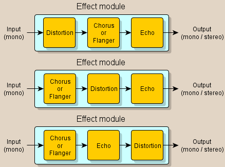
Effect module
The effect module modifies the signal by effects such as an tube distortion, chorus or flanger and echo.
In addition, at this point a stereo signal is generated from the mono signal.
There are several variants of the effect order: